
Search Results for – "slim jim"
Update to Slim Jim calculator
I have added the ability to include a known velocity factor into the Slim Jim / J Pole calculator, to help with building them with 450Ω or 300Ω feeder. Also, here is a tested and reproducible Slim Jim for 70MHz (4m) made with 450Ω balanced feeder:
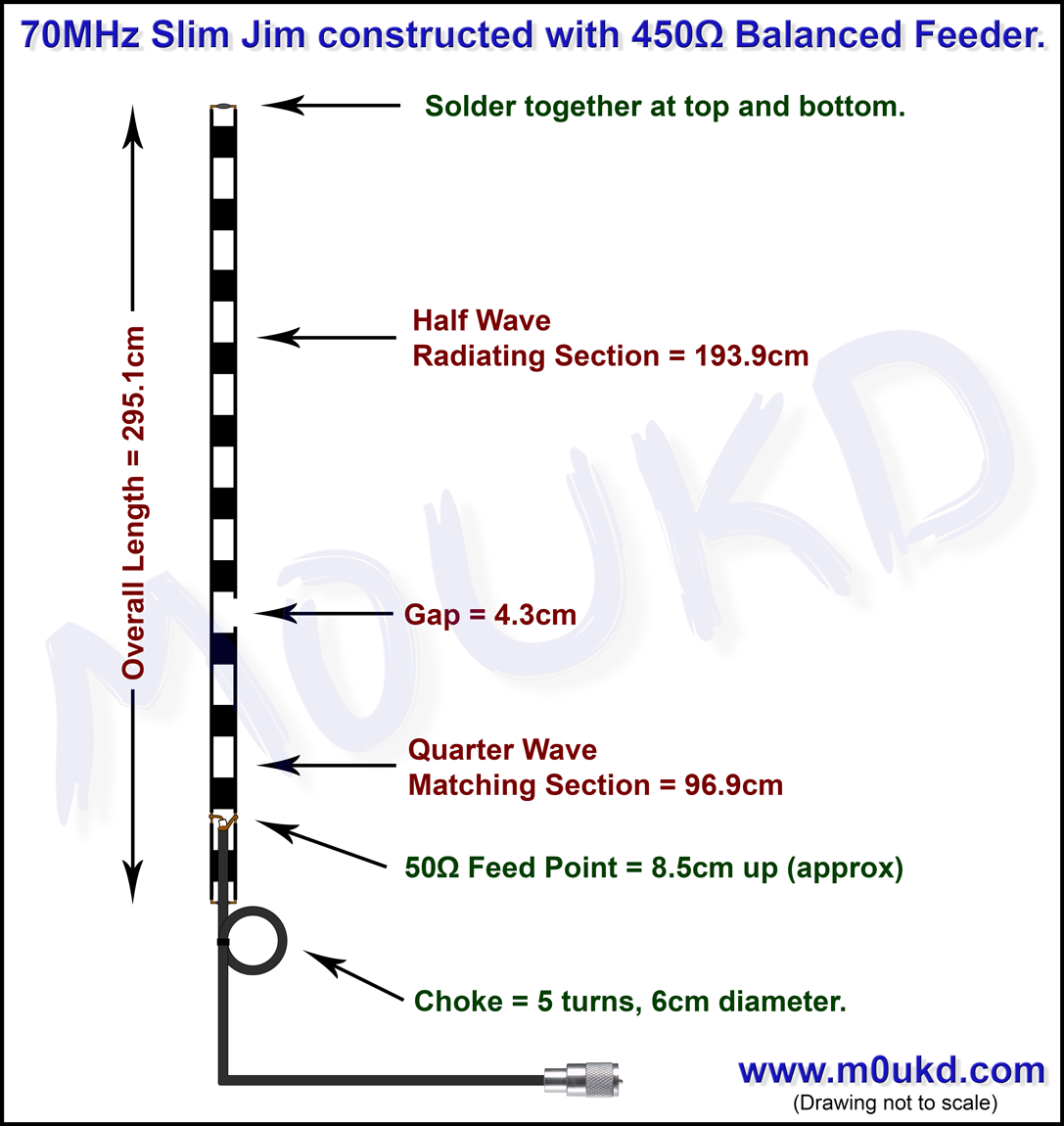
70MHz Slim Jim constructed out of 450Ω feeder
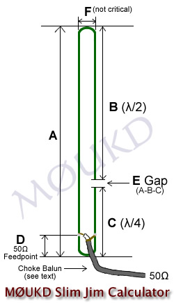
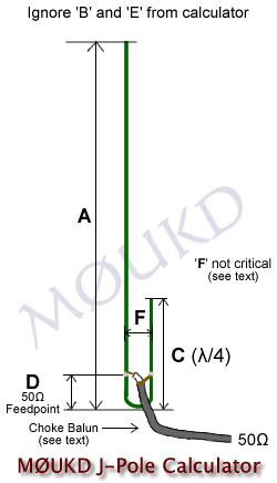
Slim Jim and J Pole calculator
Before we start, be prepared to experiment! The calculator will get you close (or spot on if you're lucky), but there are so many variables. You can use an antenna analyser to easily find if you are too long or short. Tuning can be done by adjusting the 1/4 wave stub length and the feedpoint position. To bring the resonant frequency up, shortern the 1/4 wave stub. To bring the resonant frequency down, lengthen the 1/4 wave stub. Bandwidth is much narrower than a centre fed dipole due to the tuned matching section, which makes building the antenna more critical. Tuning should be done out in the open and away from the ground, or the final mounting position if possible. OK, now thats out of the way, lets continue...
This calculator can be used to design a Slim Jim or a J Pole antenna. The Slim Jim, designed by the late Fred Judd, G2BCX, can be a great portable 'roll up' antenna, if made out of 300Ω or 450Ω ladder line / twin feeder. Add a loop of string to the top, and hang it on a tree branch, use it with your handheld transceiver, then roll it up and put it in your pocket when done! A Slim Jim for 2m (145MHz) will be 1.5 metres long, and 70cm (433MHz) will be 0.5 metres. Alternatively, for permanent installations, the copper tube or aluminium J-pole is a good choice. I have had good success with both, but regularly use the balanced feeder Slim Jim mounted on a 9m fibreglass pole, as can be seen in the photo at the bottom of the page.
It is recommended to use some sort of choke at the feedpoint. Three turns (for 145MHz) of the coaxial cable around a 40mm former (PVC pipe etc), or taped up and hung freely is adequate. Five turns, 6cm diameter for 70MHz. I have also used a clip on ferrite or two for VHF. As with any balanced feed antenna, this will help prevent the braid of the coaxial cable from radiating, and becoming part of the antenna, and therefore affecting SWR and performance. You can check the effectiveness of the choke by touching the coax below the choke and if the SWR changes significantly, your choke is inadequate.
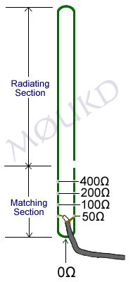
The spacing between elements, I have shown as 45mm on 2 metres. This is not critical. It will have some effect on where the 50Ω feed point is, but i'm sure you'll find it! The critical lengths are B, C, and E then adjust the feedpoint to find a perfect match. Ignore B and E if building the "J pole". All dimensions should be between the closest metal to metal (inside), not centre to centre. a 1.0:1 SWR will be possible when the antenna is working perfectly. If you cant get it perfect, the length of the elements may need adjusting or the choke is not adequate. Just remember, when adjusting elements, 1cm shorter on 'C' would equal 3cm shorter off 'A'!
*Velocity Factor: I have added the ability to select the velocity factor of your conductor. It is set by default to 0.96, which is for bare copper or bare aluminium. If you use balanced feeder such as 300Ω or 450Ω, adjust it to 0.9 (or set to the cable manufacturers specification if available). The diameter of the elements will also slightly affect the length.
50Ω feed point: The 50Ω feed point is a starting point and should be adjusted up and down until you get a 1.0:1 SWR (or as close as possible) with your antenna. You could even use a 4:1 coax balun and feed it higher up the matching section. If you can't find the 1:1 point, the elements are either too long or too short. This is where an analyser comes in handy. Tuning can be done by adjusting the length of the 1/4 wave stub 'C'.
I made one for 4m (70MHz) which is 3 metres long. The quarter wave matching section can be made horizontal, with the half wave radiator section vertical, 90° to it if space is an issue, although this will affect radiation pattern slightly. Just remember the whole antenna needs to be in the clear, away from any objects, especially conductive objects!
So, how does this thing work?
The Slim Jim, similar to the J-pole, is in fact a half wave end fed dipole, in the Slim Jim's case, an end fed folded dipole. As with all folded dipoles, the currents in each leg are in phase, but in the matching stub they in phase opposition, so little or no radiation occurs from the matching section. You may think how can you say this is a dipole, when its just one element? Well, contrary to popular belief, the dipole is so named because it has two electrical poles, not two physical poles. Wouldn't that be a di-element!? Just like a magnet has two magnetic poles, a North and a South, we have two electrical poles, a Positive and a Negative. Being a half wave, there is always two opposite poles on the tips at each half cycle. Any half wave antenna is actually a dipole.
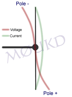
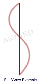
To help explain this, I have drawn above what happens to the voltage on a half wave element during one cycle. You can see, there are 2 poles, one positive and one negative at each half cycle. Hence, 'dipole'. As its a half wave element, the wave is opposite at each end. Unlike the full wave example on the right, where the wave will join up if you imagine placing it on top of itself.
Hopefully, this explains things, and shows that the Slim Jim is actually a half wave dipole. A dipole, is usually fed from the centre, where the impedance is about 70Ω. This provides a reasonable match to 50Ω coaxial cable, and is why the centre fed dipole is so widely used. A dipole can be fed anywhere along its radiator, for example, the windom is 'off centre' fed at the 200Ω point, and an end fed half wave will give a very high impedance of up to around 5000Ω.
So, we are feeding this half wave antenna from a high impedance point, which needs to be matched to 50Ω coaxial cable, and is where the 'J Integrated Matching' (JIM) quarter wave matching section (λ/4) comes in. With the Slim Jim, you have the option to select the exact impedance you want, typically 50Ω. With the centre fed dipole, you have an impedance of around 70Ω.

The matching section is just a matching section and does not radiate significantly. The 'equal' but opposite currents can be seen in the EZNEC model of the J Pole above, however, as one end of the matching section is not connected, it will have an infinite impedance. The other end of the matching section is connected to our radiator and although this is a high impedance point, it is not infinite, which is why some slight radiation of the matching section is inevitable. The more perfect the antenna is operating, the less this will be an issue as we will have the highest possible impedance at the base of the λ/2 radiating section if it is a perfect half wave.
The 50Ω point can be found once you have built the antenna to the correct dimensions. Have the antenna out in the open, then move the feedpoint up and down small amounts, and when a 1:1 SWR is found, fix them there. An example of what the different impedance points may look like are shown on the image to the left. The calculator above will give you a good starting point, although spacing between the elements, velocity factor and other differences will have an effect on where this actually is.
Slim Jim vs J Pole
There are many rumours on the Internet, claiming that the Slim Jim has better performance than the J Pole. Simulation (and common sense) suggests that they are practically identical. John Huggins KX40 covers this question on this page. It is likely that any real world tests that show the Slim Jim to have better low angle gain than the J Pole is due to the (sometimes) poor way people tend to mount the J Pole by grounding the base to a mast or not choking the feedpont, as opposed to the Slim Jim usually being mounted freely. I build my J Pole antennas as a J and mount them insulated from any mast.
Here is a working 4m Slim Jim constructed out of 450Ω feeder, the stuff with the solid core. I have built two of these and it should be easily reproducible and work 'straight out of the box'!

Click image for larger version.
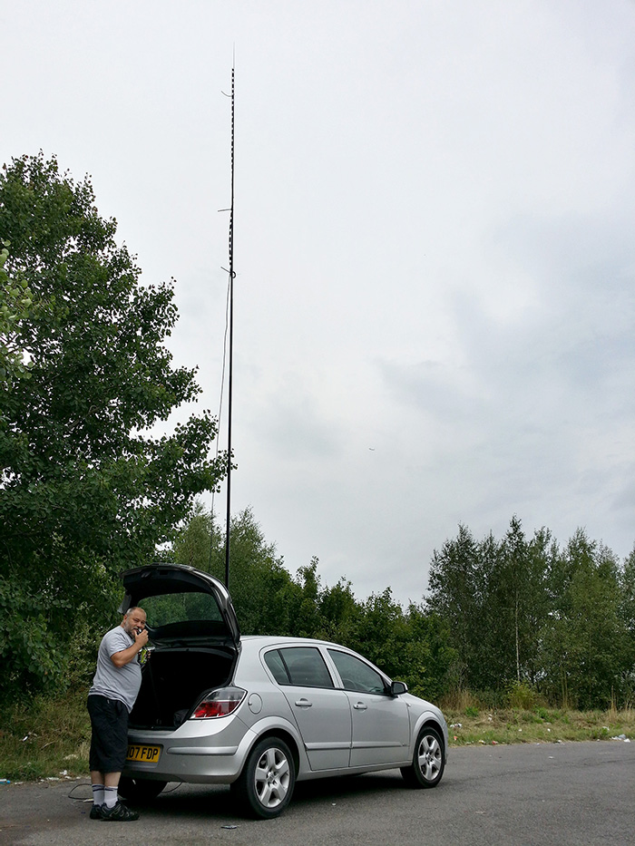
Dave M0TAZ using a 450Ω feeder Slim Jim on 70MHz.
Below is a J Pole that I built for 70cm. SWR is <1.5:1 from 430MHz to 440MHz.

I hope this has been of help to you. If you decide to build any of these, I'd like to know what you think of it and how you got on. Please leave a comment! Thanks, 73 John.
Working Happisburgh Lighthouse on 70MHz
Selim M0XTA went to Happisburgh Lighthouse for the Lighthouse On The Air weekend 2015. He set up a 70MHz station on top of the lighthouse, using a ⅝ λ vertical. I had a listen from home and could just make out a signal in the local noise I get on 4m at home, so I decided to go out portable and give it a try.

The 70MHz slim jim on 10m pole
I set up a slim jim made from 450Ω feeder on a 10 metre fibreglass pole on a small local hill (away from the QRM) and used the Anytone AT588 with 50w on FM. There was some slow QSB, but we made the contact. He was 105 miles from me (see map). Not bad for no beams and FM!
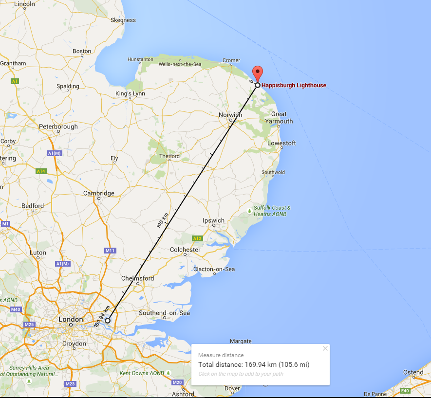
Happisburgh Lighthouse Distance Map
I took a tiny bit of video on my phone, which is below.
I finally put up a dipole for 70MHz (4m)
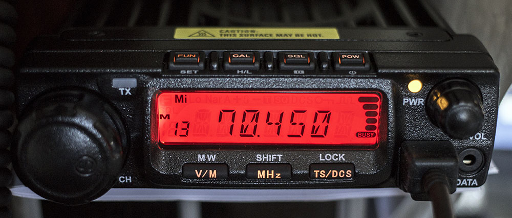
Anytone AT-588 on 70MHz
Today, I finally built a ½ λ dipole for 4m. I have previously been using a folded ½ λ dipole made out of 450Ω balanced feeder, suspended in the loft, which is not ideal. I still had the coax outside on the roof and the pole which were both used previously for my 2m/70cm co-linear, which has been relocated to the chimney, so once it was built, it was simple enough to put up. (more…)
Calculators
This page contains various javascript based calculators for electronics.
- Slim Jim and J-Pole antenna calculator – Build a cactus for any frequency.
- 1/4 Wave Ground Plane antenna calculator – Build a simple quarter wave with radials.
- Ω Ohm’s Law Calculator Ω – Enter 2 values from Voltage, Current, Power or Resistance, to find the remaining two.
- dBm, dBW, µW, mW, W, kW and MW calculator – Calculate between dBm, dBW, µW, mW, Watts, Kilowatts and Megawatts.
- ERP & EIRP Calculator – Calculate effective radiated power from your antenna.
- Resonant Frequency Calculator – Calculate the resonant frequency of a parallel inductor and capacitor tuned circuit.
- PI attenuator calculator – Calculate the resistor values for a PI attenuator.
- T attenuator calculator – Calculate the resistor values for a T attenuator.
- Air cored inductor calculator – Build an inductor of any value!
- Inverted Vee Antenna – Calculate the wire length for an inverted vee antenna.
- Parallel Resistor, Inductor or series capacitor calculator – Work out up to ten values, simply.
- Electricity cost calculator – Work out what an appliance costs to run if you know your electricity rate in kWh!